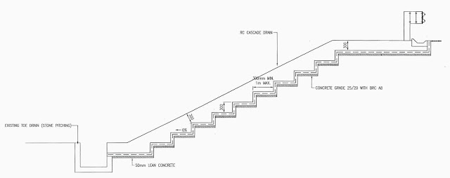
- Drain shall be excavated besides the shoulder drain at interval specified by the Engineer. The width and depth shall be as specified in the drawing.
- Gradient of excavation is checked against the requirement. Upon approval from the Engineer, lean concrete at thickness of 50 mm is laid along the drain.
- Followed with the installation of BRC A8 (or as otherwise specified) on the lean concrete. Spacer blocks are used to ensure required thickness of 50 mm is achieved. Concrete grade 25/20 is used.
- Formwork is set-up for drain walls and concrete is poured into the formwork.
- The concrete is let to cure for at least 2 days prior to dismantling of the formwork.
- The construction shall be based on requirement imposed as per drawings.

Labels:
drainage
Cascade Drain (Chute Drain)
Posted by
Engineer Malaysia
Labels:
drainage
Shoulder Drain (Pre-cast block)
Drain shall be excavated
besides road shoulder at 100 mm spacing from the existing guardrail post. The width and depth shall be as specified in
the drawing. The length of excavation
shall be as specified in the bill of quantity.
Gradient of excavation is checked against the
requirement. Upon approval from the
Engineer, lean concrete at thickness of 50 mm is laid along the drain.
The pre-cast blocks are then
laid properly as per drawing, ensuring the profile and layout to follow the requirement.
Posted by
Engineer Malaysia
Labels:
drainage
Sub-soil Drain: Type II
- The emergency lane affected shall be cut using diamond cutter.
- The 1200 mm (required depth) by 400 mm (width) trench shall be excavated.
- The non-woven geo-textile shall be laid manually inside the trench.
- The 150 mm diameter porous pipe is then laid manually inside the trench with specific gradient that will ensure easy flow of water.
- Followed with backfilling of 20 – 25 mm single size aggregate to the required thickness.
- No fine concrete is then poured to the thickness as mentioned in drawings.
- Bituminous layers are then laid as required in scope of works.
Posted by
Engineer Malaysia
Labels:
drainage
Sub-soil Drain: Type I
- The 1200 mm (required depth) by 400 mm (width) trench shall be excavated.
- The non-woven geo-textile shall be laid manually inside the trench.
- The 150mm diameter porous pipe is then laid manually inside the trench with specific gradient that will ensure easy flow of water.
- Followed with backfilling of 20 – 25 mm single size aggregate.
- Sand backfilling shall follow.
- Earth fill shall be laid and compacted to get appropriate compaction.
Posted by
Engineer Malaysia
Labels:
guardrail
Concrete Pad
- If concrete pad is required, the guardrail post is extracted first from the footing.
- A square pit by the dimension of 300 mm x 300 mm x 200 mm (as shown in the drawing) is dug.
- The guardrail post then place into the pit, suspended to the required height. String can be used to ensure uniform level is achieved on all the selected raised guardrails.
- Concrete grade 20 is then poured into the pit, properly compacted and let to cure for 3 days.
Posted by
Engineer Malaysia
Guardrail Works
Guardrail Jacking
- Guardrail to be raised is demarcated and confirmed at site with the Engineer representative.
- Depending on type of footing surface, the height of post shall be 710 mm for concrete surface and 800 mm for non-concrete surface. The following drawing shown the final height of guardrail as intended after the jacking.
Guardrail Jacking (using heavy duty hydraulic jack or chain block)
- The equipment is positioned adjacent to the identified post.
- Manually, the post is raised to the required height as mentioned in (ii) above.
- Upon achieving the required height, the footing of guardrail post is properly compacted as to ensure that the post shall not ‘slip down’.
Posted by
Engineer Malaysia
Subscribe to:
Comments (Atom)


